May17
Monthly Archives: May 2021
May16
Back to the Keyboard
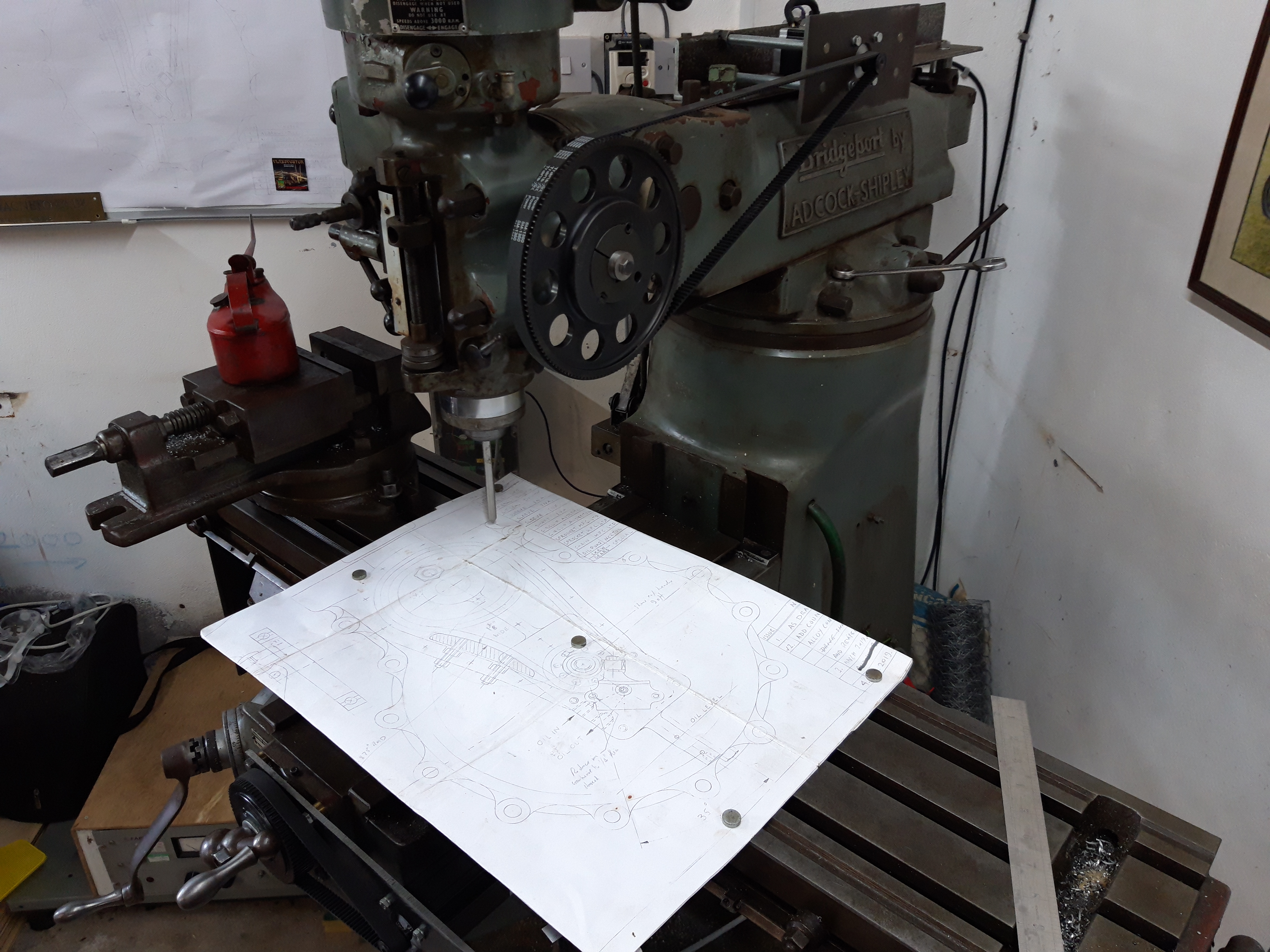
While we’re waiting for the cases to be cast and heat treated, I’ve started to write some GCODE for fly cutting the mating faces. With such large components travel on the Y axis is very close to the limits, so a trial run over a set of drawings is a must!
The position of the spindle centre is also critical, and this afternoon I brought it forward. I hadn’t done this before but it was fairly straightforward and with Bob’s assistance now in the right place. Bob remains unconvinced that CNC is better than handle twiddling!
I think we’re going to be ok without resorting to larger machines. Great news as it is VERY close to the limit!
May12
Huge Scissors!
Getting an accurate reading from the press proved difficult, any movement was a combination of everything. All the bending moments of the long bolts, give in the jack and twist of the assembly. Bob wrote off that method and we moved onto plan B.
Plan B. Often this is the most successful of all plans, I do wonder sometimes why anyone bothers with plan A? Would NASB have been more successful than NASA?
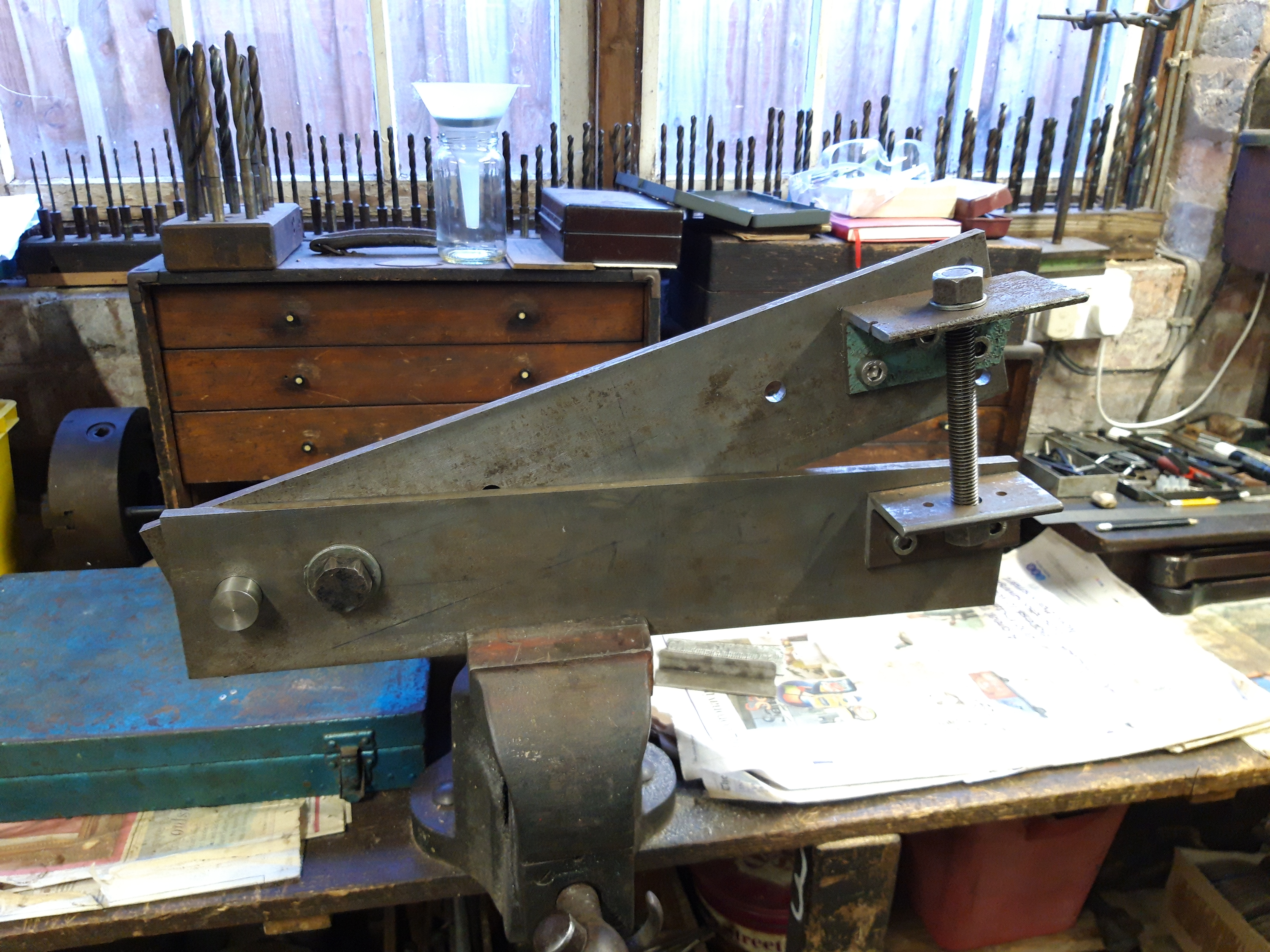
Anyway, plan B. Bob made a special tool acting like huge Scissors. In order to twist the flywheels around the crank pin, two mandrels will be fitted into the existing holes opposite the crank pin. The tool inserted between the wheels locate on the two mandrels. When opened or closed using the thread and nuts, the scissors will twist the wheels.
There’s plenty of leverage so it ought to work!
May11
Pressing a twist
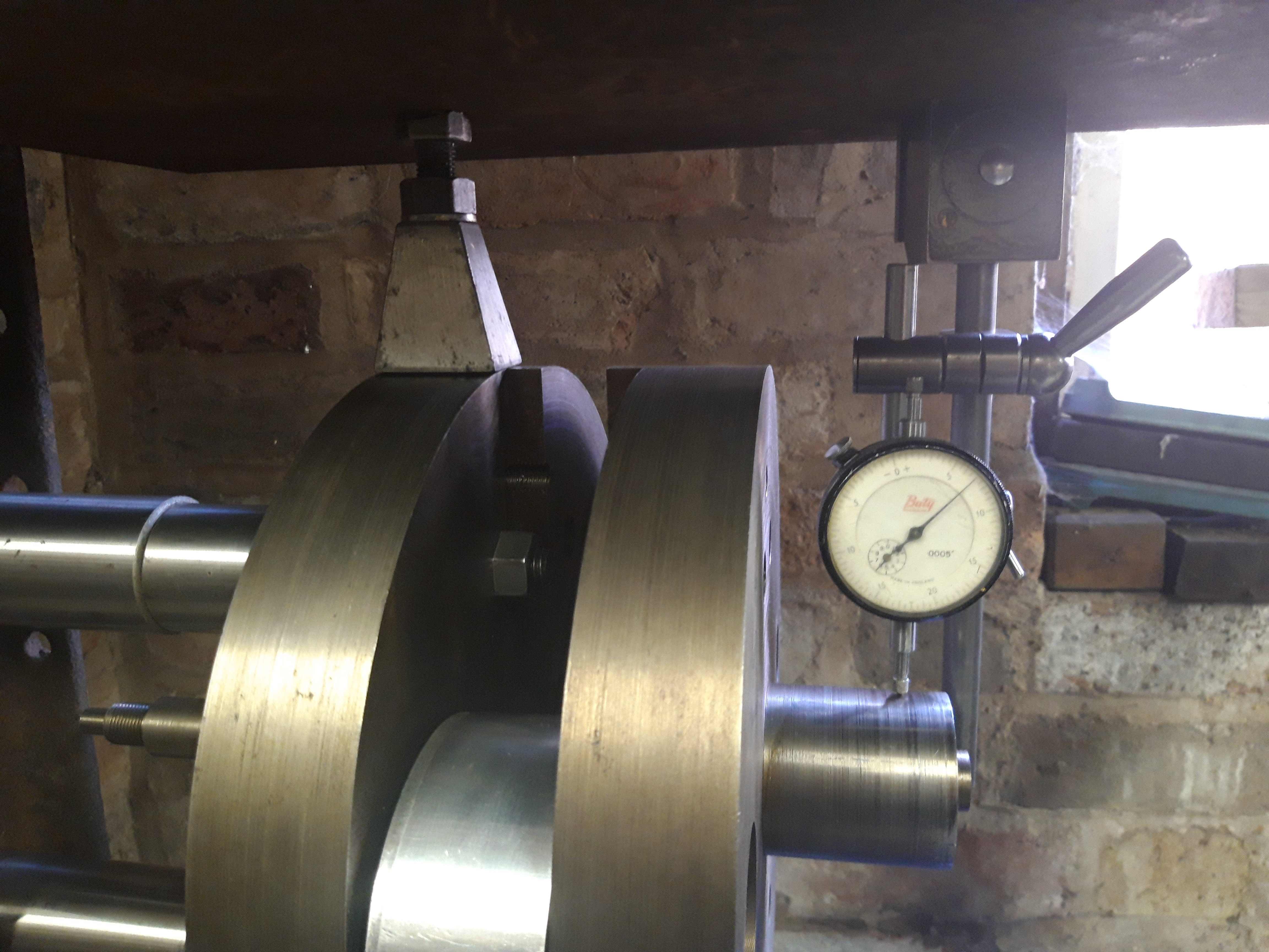
Into the press for an asymmetric push, the idea is to move the flywheels around the crank pin. A sound plan, but unfortunately the flex on the long bolts made it difficult to get a decent reading on the DTI.
Getting a twist reliably measured to 7 thou was not possible, so another think is required.
May9
CAD Model.
The flywheels have been clocked and have a run out of around 15 thou. Ideally this needs to be less than 5, so the wheels need to be both jacked apart and twisted around the crank pin. Accurately!
Jacking the wheels apart is fairly straightforward, but twisting them around the crank pin is more tricky. The plan is to mount them on the press, then use the press to push them around the crank pin.
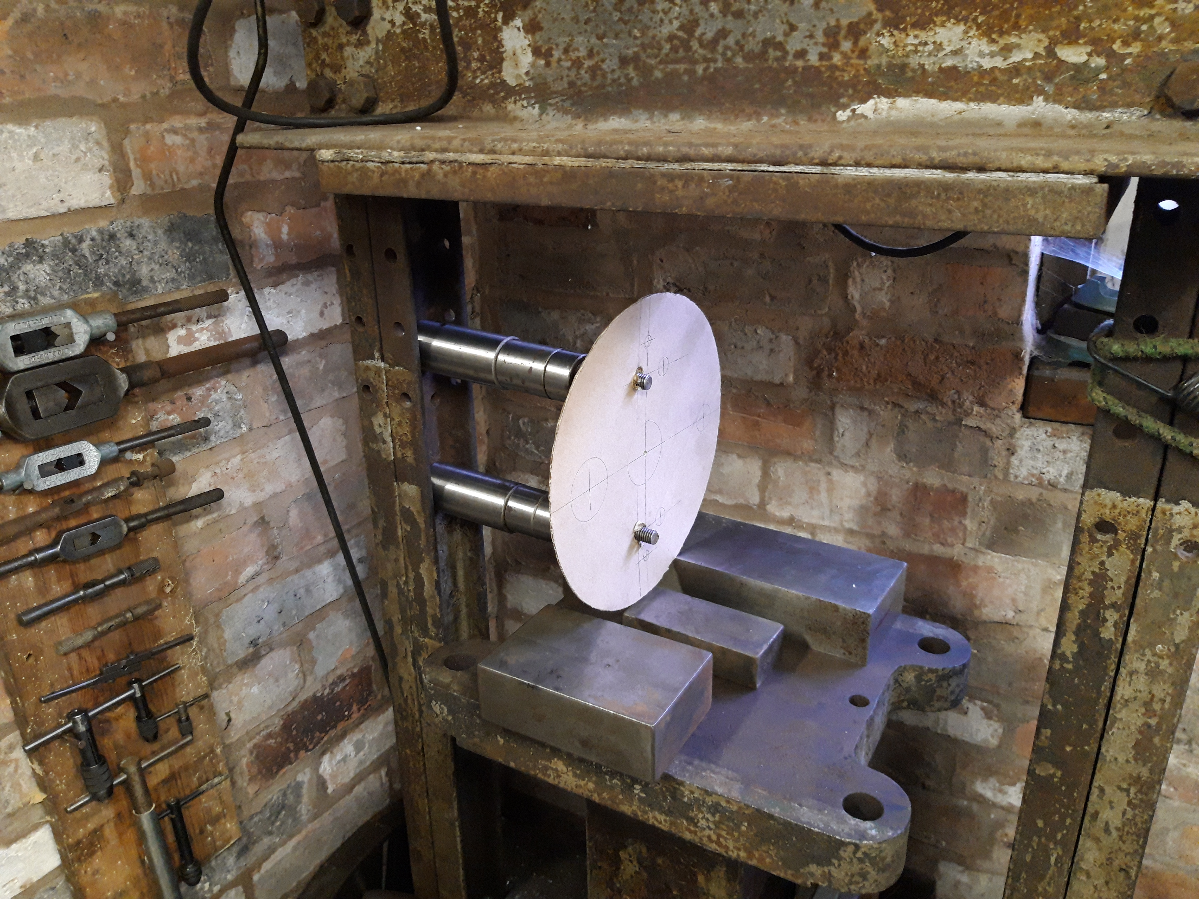
The photo shows the CAD model (Cardboard Aided Design 😁😁) for bolting the wheels to the press. Bolts are in place ready for the heavy lift of the crank assembly onto the press.
May8
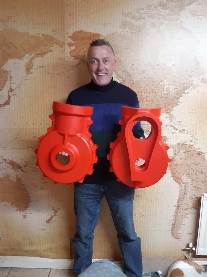
Patterns completed!
It’s taken a while longer than expected, but the patterns are finished and ready to take to the foundry. Excellent work from Dave and I can’t wait now to see a set in metal. The picture gives you a good idea of the size of things 😁
The plan is to get a couple of sets making, so I can get a set machined in basic order to hold the barrel. This will be a full sized mock up to get the frame started, while the other set gets fully machined.
Bob has the machining plan sorted and a bit of a job on learning the CNC operation on the Bridgeport – but it’s easier than you’d think so I’m sure I can explain it!