It’s a Centaurus!

Standard

Looking through the parts I have in a little more detail, the cylinder I have is definitely Centaurus. This isn’t good news as I was hoping to swap it for the cylinder off a Hercules complete with matched internal parts. This might not be so easy now.

The sleeve drive for the rear bank of cylinders on the Centaurus is on the rear of the cylinder. I can see why they did it, but it doesn’t help me now. That’s the major give away as otherwise they’re the same.

I could of course use all Centaurus parts and make it 2.96 litres instead of 2.75. Or make two? A small one and a big one? Hmmm….

Parts!!

Standard

I finally got my hands on some parts and first impressions are that they’re big! Not unfeasibly large, just big – and I love it.

A job lot of spares came up at the right price so I took the lot, even though I suspect some of them are Centaurus parts. One sleeve is slightly longer than the other, which leads me to believe it’s from a Centaurus. I have three heads, two aluminium and one cast iron.

I prefer the look of the iron heads, but they weigh a tonne! Not as heavy as the crank and rod assembly I picked up. That’s too heavy to lift onto the bench!!

It will take a couple of days to plough through what I have and decide which parts (if any) are serviceable. I’m still holding out for a matching set from one engine, but the special spanners are proving to be quite elusive.

Those parts are out there somewhere I know it!

Head Case!

Standard

Well actually no. What we have here is a freehand sketch of the crank case, one side. The sleeve drive side (or timing side I suppose if you follow convention). To assist the pattern maker this view is quite useful. It’s also good for anyone wanting to visualise the finished engine.

The chain and sprockets driving the sleeve will be visible with the side plate removed. The side plate will house the oilways for feeding the shafts and the ignition pickup. I’ll post a pic of the side plate shortly.

Bob is finalising the full sized drawings, after which the design work will be all but complete. The only remaining task is to source a Piston and Sleeve along with a few extra parts. I’m waiting until I have those in my hand before I press the tit on the pattern maker.

Parts wise I’m waiting for people to come back to me regarding a special spanner to remove the Bristol cylinder. I can make one if necessary but I will still need to find a nut first! It’s a slow process…..

Sleeve drive.

Standard

Finished drawing of the sleeve drive by the talented Mr. Bob. As it turns out having the sleeve drive shaft rotating in the same direction as the main crankshaft really helped us. I’m sure that Sir Roy Fedden didn’t imagine we’d be doing this to his state of the art Aero engine some 70 odd years later! But even so, he no doubt faced the same design hurdles (and some more!).

Chain drive will be easy to achieve and adjust. The oil feed will be modified however as it is much easier to oil the sleeve ball joint by taking a drilling down the centre of the shaft. This means we won’t be able to run a points cam on the outside, so an alternative ignition system will need to be found. I think a hall sensor located close to the sleeve drive sprocket is probably the best solution, but I need to do some research.

Great progress though, I just need to get my hands on some parts first. Fingers crossed!

Hunting for parts.

Standard

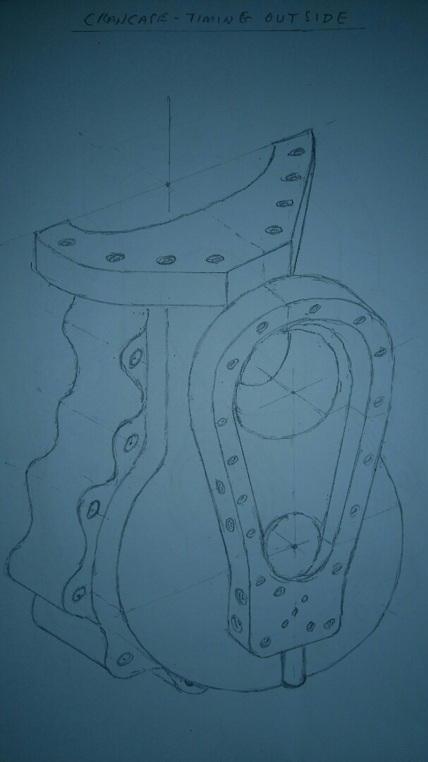
Today I managed to get my hands on a Bristol Hercules engine! The contact I made a few weeks ago at the Newark aero jumble came good, and true to his word Graham had a few engines around. The one in the picture didn’t look too bad on first inspection, but it had stood with no exhaust manifolds for some time and the sleeves were quite rusty. Some of them looked pretty bad, I doubt that the barrels could be removed without causing damage. (and that’s the last thing anyone wants!).

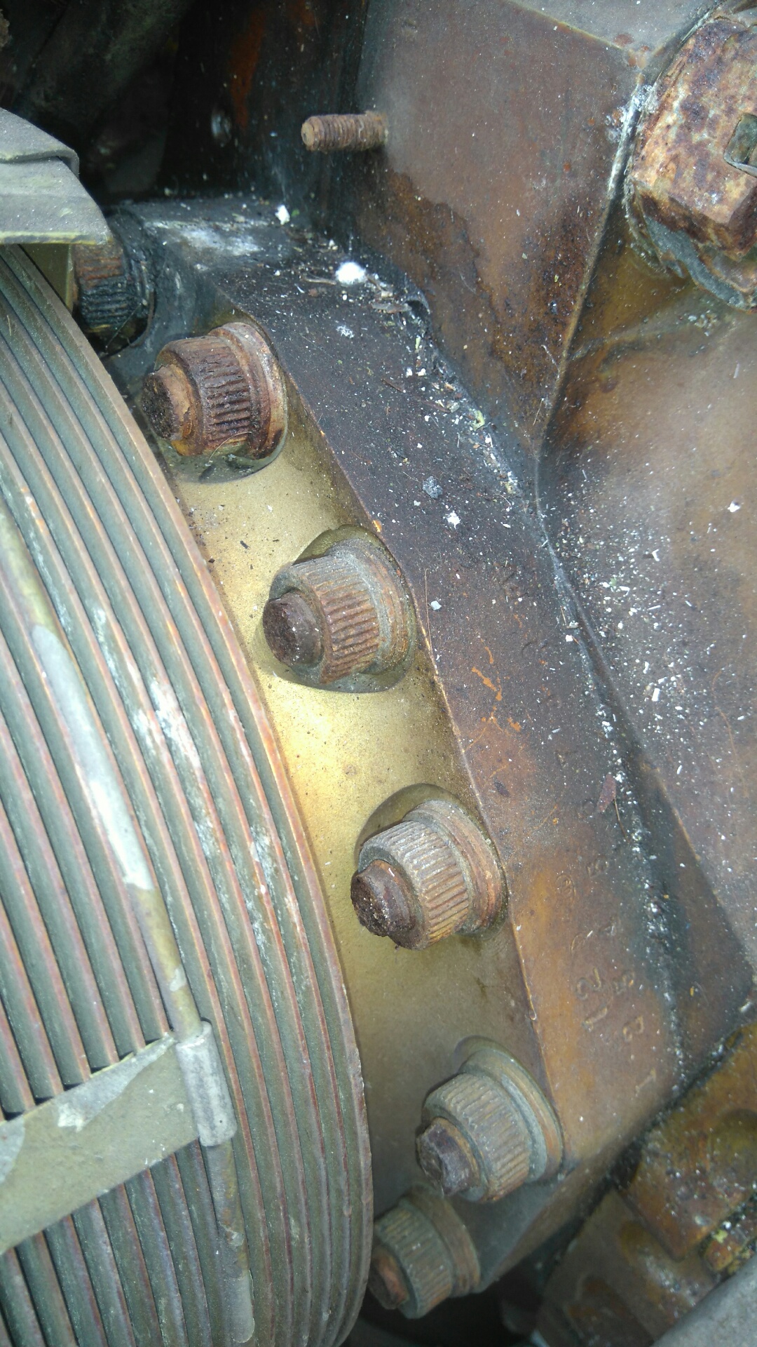
However, there’s another engine stored elsewhere that is apparently in much better condition. I will need to go back again to see it, as access to that part of the airfield needs to be pre-arranged. Graham is kindly sorting this out, along with (hopefully) the loan of some special spanners. The nuts holding the barrels on are almost splined and will certainly require care in removal to avoid damage.

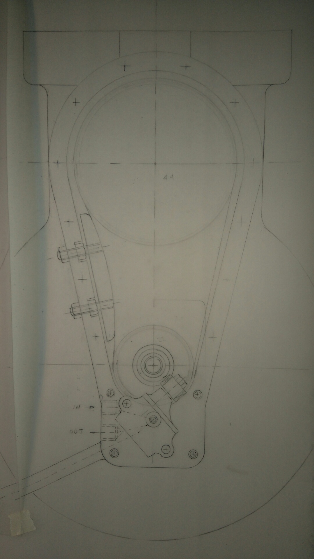
Looking at the amount of room to swing a spanner, particularly on the rear bank of cylinders, an ordinary hex nut would be no use. You couldn’t swing a spanner through the 60 degrees required to get on the next flat, so Bristol came up with a solution.

Graham seems a nice chap and is willing to help. With any luck, this time next week I might have some actual parts!

Bob’s calculations

Standard

Just a quick scribble as he puts it! But really its a fair amount of work and very clever. With Google and computers at our disposal its all too easy to take things like this for granted. Given the size of two sprockets and length of chain, work out the distance between the centres of the sprockets. Easy!

But this is proper old school engineering. No computers, no Google. Not even a calculator! You need to know the formula and do the maths.

Be like Bob!

Driving the sleeve

Standard

Talking to Bob the other day we discussed the means to drive the sleeve. As the sleeve drive shaft needs to rotate in the same direction as the main crankshaft, chain drive seems to be the easiest method.

Bob had dug out a triumph boneville manual from his library and showed me the primary drive arrangement. The drive ratio is perfect at 2:1, and the chain tensioning method would suit us too. The sprockets are physically too large, so we’d go down to 22:44 teeth from the original 29:58.

Bob showed me some calculations he’d done which are quite impressive. The distance between the shafts on the Boneville isn’t stated, but knowing the chain length and sprocket sizes he was able to calculate this. Transposing this to our sprocket sizes means that the chain tensioner will still fit. That does make life easier.

New Bench!

Standard

Not in situ yet, but here’s my new workbench round at my friend’s workshop. It’s solid as a rock and very heavy. To get it in the van (including lifting), we opted to make the top removable. A lot more work drilling and tapping, but worth it as it gives me options for fitting it in. I could make it L-shaped instead of having a straight run.

When I start looking for a decent lathe I’ll have an idea of whether the sizes I need can be bench mounted. I expect most will come on their own stands given their size, but that will add additional cost. That comes a little further down the list though. For now my next job is painting the base and rebuilding it in situ.